
Hot Water Coils
Hydronic heating coils for air handlers, rooftop units, duct systems and process air — built to your dimensions, connections and design point, for new projects and direct-fit replacements.
- Sized to your airflow, water temperatures and pressure-drop limits
- Selection report and submittal drawing before production
- Direct-fit replacements for most OEM air handlers
Have a nameplate photo, a drawing or a spec? Send it with your request — that is often enough to start.
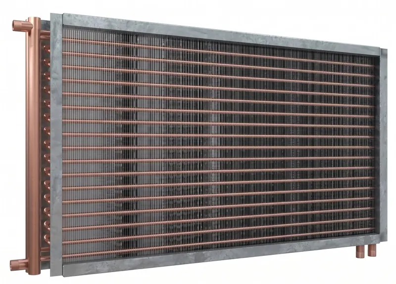
*Copper tube, copper header construction. Ratings are stated on each submittal.
How hot water coils work
A hot water coil is a finned-tube heat exchanger that moves heat from circulating hot water — or a water and glycol solution — into an airstream. Water flows through seamless copper tubes; aluminum or copper plate fins, mechanically bonded to the tubes, multiply the surface in contact with the air.
Coils are piped for counterflow, with water entering on the leaving-air side, so every row keeps the largest possible temperature difference between water and air. Circuiting — how many tubes are fed in parallel — sets the water velocity, which balances capacity against water pressure drop.
We select coils for conventional 180/160 °F boiler water and for the lower supply temperatures used with condensing boilers and heat pumps. Lower water temperature means less driving force, so those coils usually need more rows or tighter fin spacing — we size for it instead of assuming the old design still works.
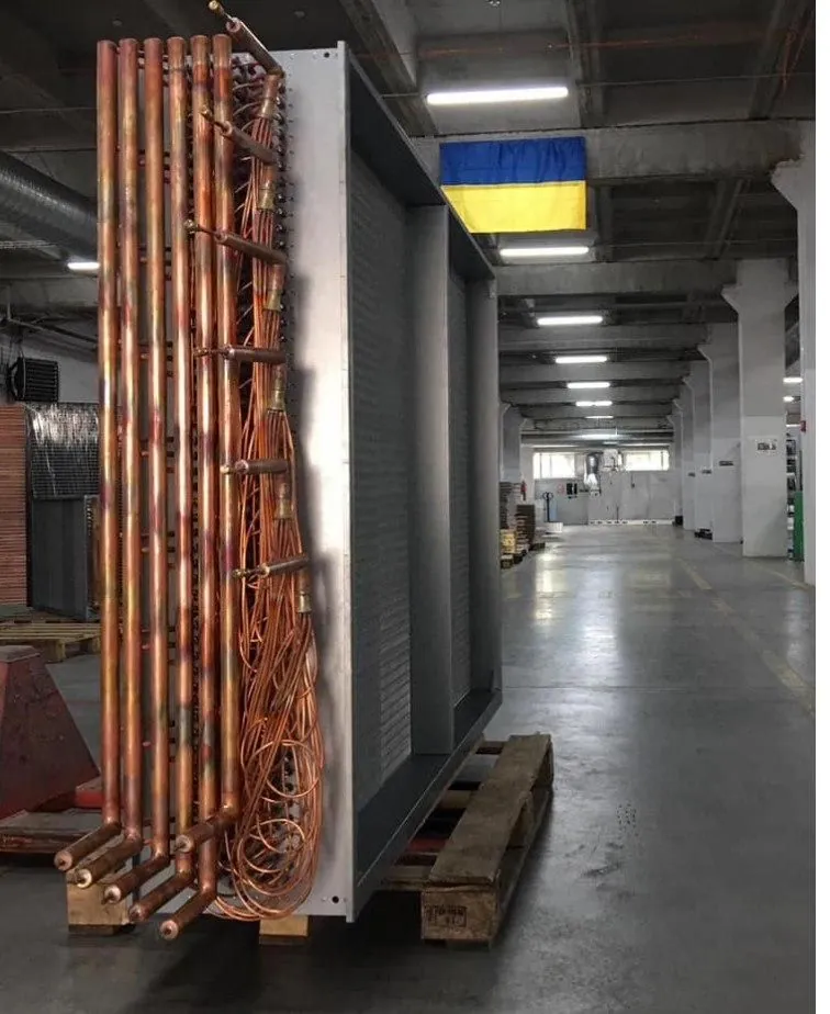
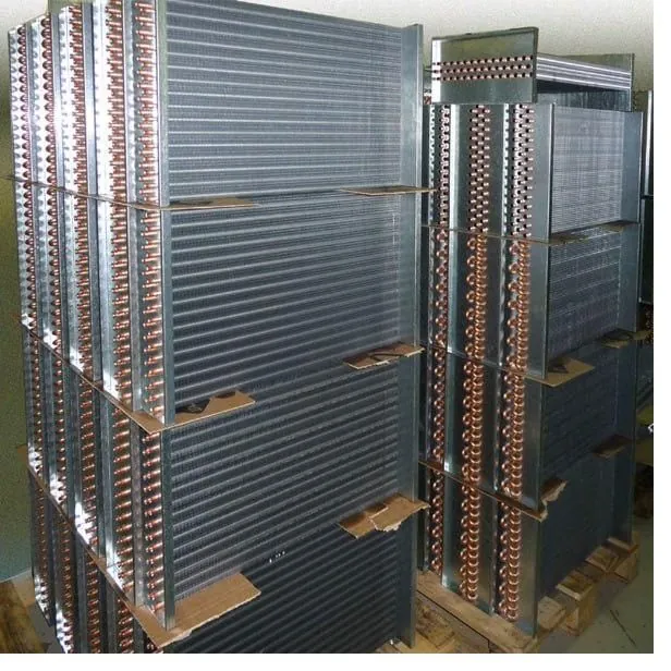
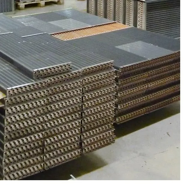
A large-face coil with copper headers, staged for shipment.
Where they’re used
Hot water coils serve every part of a hydronic heating system, from central-station air handlers to single-zone reheat.
Air handling units
Heating and preheat coils for central-station AHUs, make-up air units and dedicated outdoor air systems.
VAV reheat and duct booster coils
Compact 1- and 2-row duct coils with slip-and-drive or flanged casings for zone reheat.
Rooftop and packaged units
Hydronic heating sections for RTUs and packaged air handlers served by a central boiler plant.
Fan coils and unit heaters
Small-face coils with 3/8" or 1/2" tube for terminal units, cabinet heaters and unit heaters.
Heat-recovery loops
Glycol coils for runaround loops that move heat from exhaust air to incoming outdoor air.
Process air heating
Drying, curing and industrial make-up air, in stainless steel or coated construction where the air is corrosive.
Configurations we build
Four construction families cover almost every hot water application.
Standard AHU coils
Flanged galvanized or stainless casings that slide into air handlers and built-up systems.
Duct booster coils
Slip-and-drive or flanged casings for VAV reheat, sized to fit the duct.
Stacked coil banks
Compact 1- and 2-row duct coils with slip-and-drive or flanged casings for zone reheat.
Stacked coil banks
Compact 1- and 2-row duct coils with slip-and-drive or flanged casings for zone reheat.
Specifications
Every option below is available on any hot water coil we build. If your specification calls for something else, ask — most requests are routine.
| Component | Standard construction | Options |
|---|---|---|
| Tubes | 5/8" OD seamless copper, 0.020" wall | 3/8" and 1/2" OD; 0.025", 0.035" and 0.049" wall; 90/10 cupro-nickel; 304 or 316 stainless steel |
| Fins | Aluminum plate fin, sine-wave, 0.006" | 0.008" or 0.010" aluminum; copper; flat fin for easier cleaning; pre-coated aluminum |
| Fin density | 8–12 FPI | 4–14 FPI |
| Rows | 1–4 | Up to 8 for low-temperature water or large air temperature rise |
| Circuiting | Counterflow, selected for water velocity and pressure drop | Quarter, half, full and double circuit; same-end or opposite-end connections |
| Headers | Seamless copper, brazed | Schedule 40 steel, stainless steel, cupro-nickel |
| Connections | MPT, red brass or steel nipples | FPT, sweat, flanged, grooved |
| Vents and drains | 1/4" FPT on every header | 1/2" FPT; extended through the casing |
| Casing | 16 ga G90 galvanized steel, flanged | 14 ga galvanized; 304/316 stainless; aluminum; slip-and-drive for duct coils; intermediate tube supports on long coils |
| Coatings | None | Cathodic epoxy e-coat or baked phenolic, on fins only or on the complete coil |
| Testing | Every coil leak-tested with dry air or nitrogen while submerged | Higher test pressure, helium leak test, witnessed testing |
| Documentation | Selection report, submittal drawing, IOM manual | Material certificates, test reports, CAD files (DWG, STEP) |
Standard copper construction is rated 250 psig working pressure at 300 °F. Higher ratings use heavy-wall tubes and steel headers; the rating for your coil appears on its submittal drawing.
Capacity depends on your operating point, so we calculate it for every quote. These are the ranges and relationships we design with.
| Parameter | Typical range and guidance |
|---|---|
| Face velocity | 400–600 fpm. Heating-only coils can run faster if the air pressure drop is acceptable. |
| Entering air | 40–65 °F mixed air is typical. Outdoor-air preheat goes lower and needs glycol or a freeze-protection strategy. |
| Entering / leaving water | 180/160 °F conventional; 140/110 °F, 130/100 °F and lower for condensing boilers and heat pumps. |
| Water velocity in tubes | 2–6 ft/s typical. Watch for laminar flow with glycol at low temperatures — it cuts capacity sharply. |
| Air pressure drop | Coils in series without an 18 in. access space: 0.75 in. w.c. max combined, dry, at 500 fpm (ASHRAE 62.1). |
| Fluid | Water, or ethylene or propylene glycol at 20–50%. Glycol lowers capacity and raises pressure drop. |
| Water pressure drop | Held to your pump design limit — state it on the request. |
Designing for low-temperature hot water? Return water below roughly 130 °F lets condensing boilers actually condense. Selecting coils for a lower supply temperature and wider water ΔT is one of the cheapest efficiency gains in a hydronic system; the selection report shows the row and fin trade-off.
Every quote includes a selection report — capacity, leaving conditions and pressure drops for your design point — and a submittal drawing you approve before production.
For quick checks and budget sizing. Your quote comes with a full computer selection.
Worked example
A 24 in. × 48 in. coil has 8.0 ft² of face; at 4,000 CFM that is 500 fpm.
Heating air from 50 °F to 90 °F: 1.08 × 4,000 × 40 = 172,800 Btu/h (172.8 MBH).
With 180/160 °F water: 172,800 ÷ (500 × 20) = 17.3 GPM.
Send us these numbers — the selection sets rows, fin density, circuiting, APD and WPD.
Every quote includes a selection report — capacity, leaving conditions and pressure drops for your design point — and a submittal drawing you approve before production.
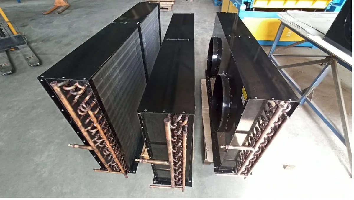
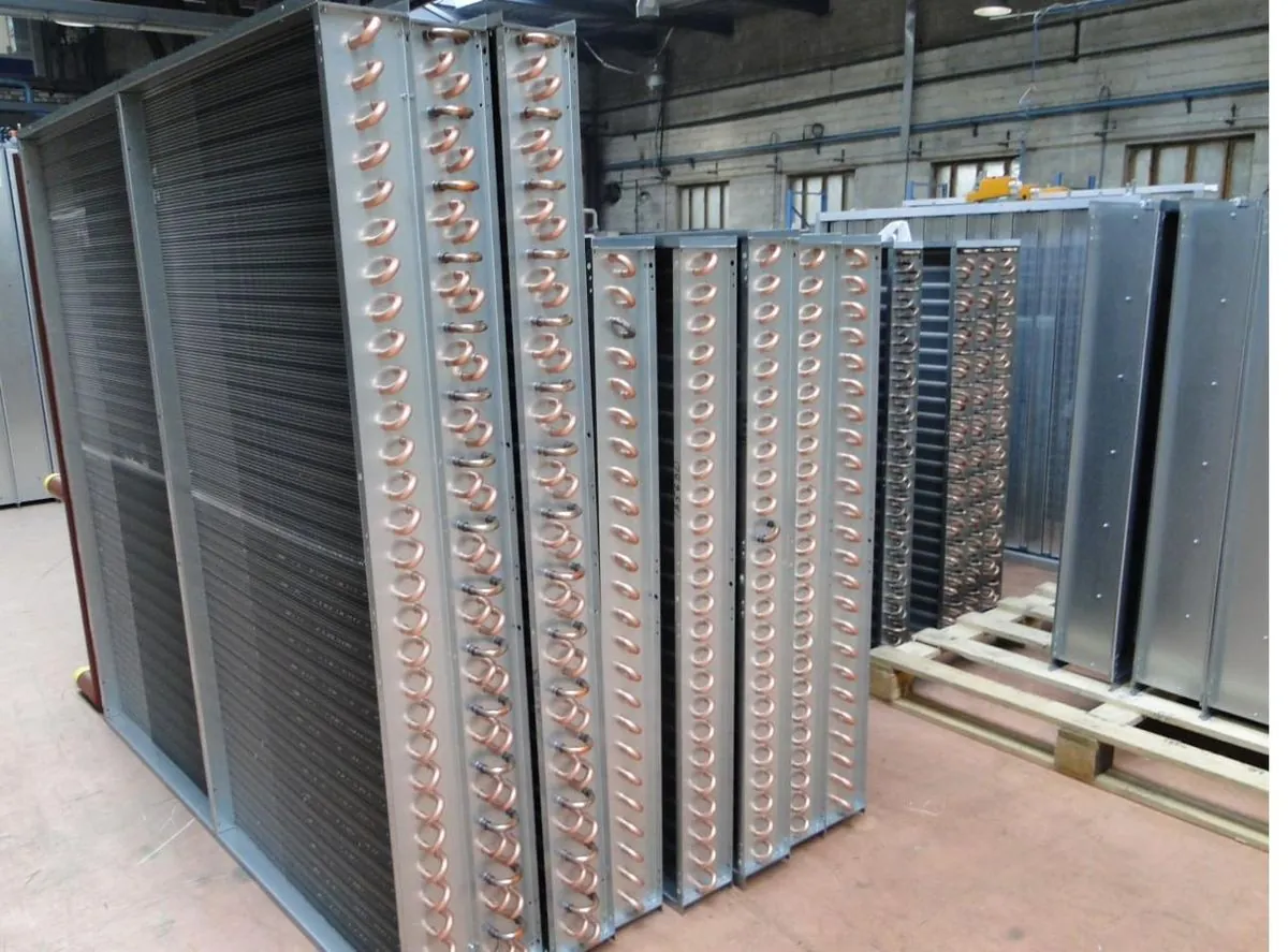
From the production floor
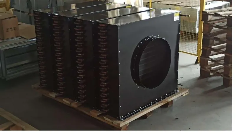
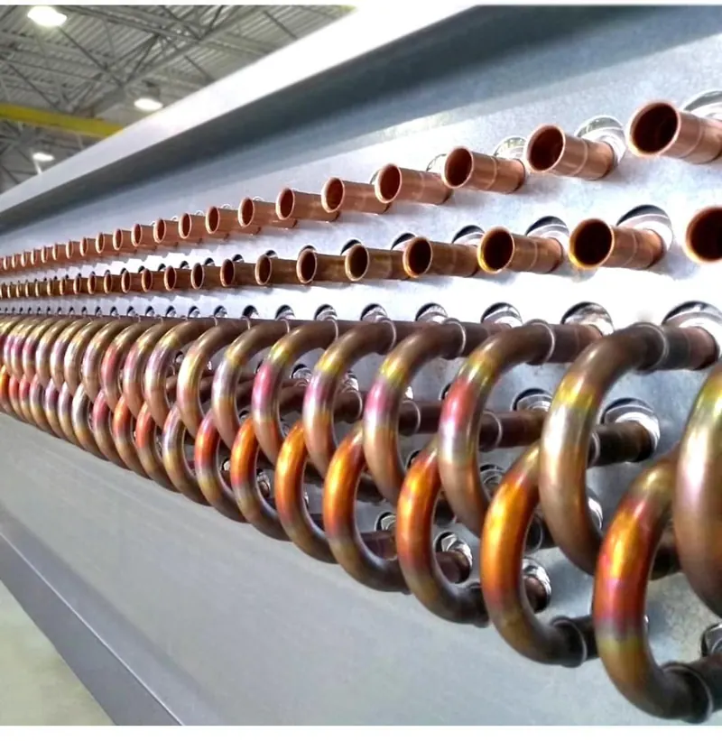
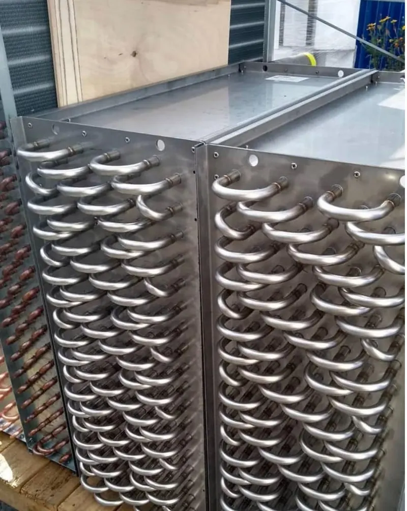
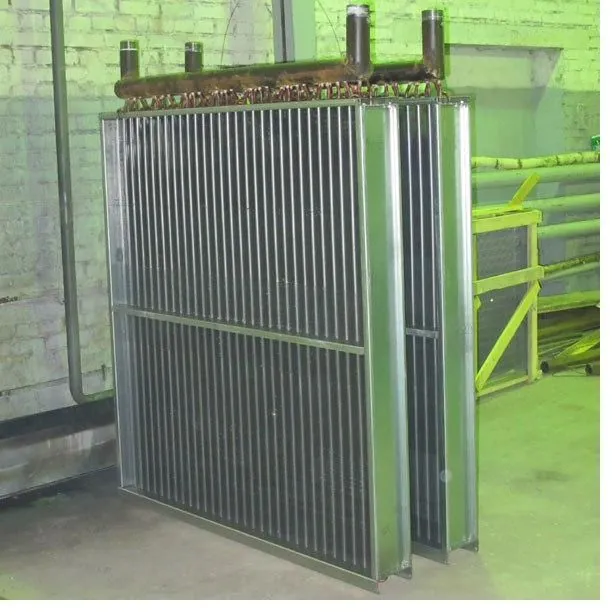
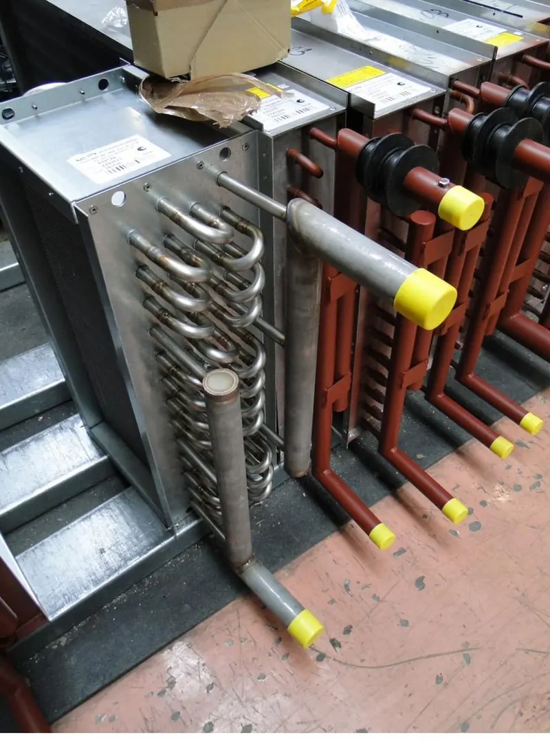
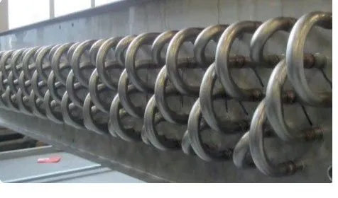
Hot water coils, parts and assemblies in production.
Installation and freeze protection
Key points. The full procedure is in the IOM manual supplied with each coil.
- Pipe for counterflow: supply to the header on the leaving-air side, return from the entering-air side.
- Connect supply to the lower connection and return to the upper one, so the coil fills from the bottom and air collects at the vent.
- Open the vent after filling and again after the first heat-up; drain from the low-point plug.
- Hold the header nipple with a backup wrench when tightening pipe — twisting loads crack header joints.
- Support piping independently and allow for thermal expansion; coil connections are not pipe supports.
- Fit isolation valves, a strainer and unions so the coil can be serviced without draining the system.
- Coils that see below-freezing air need a strategy: glycol, continuous circulation (for example a coil pump), a correctly placed low-limit thermostat and good upstream air mixing. Never rely on a closed valve.
Frequently asked questions
How many rows does a hot water coil need?
One or two rows usually cover VAV reheat and booster duty with 180 °F water. Air handler heating and preheat coils typically need two to four. Lower water temperatures, large air temperature rises or tight water-flow limits push toward more rows. The selection report shows the options side by side.
Can you match my existing coil so nothing else has to change?
Yes. We match fin height and length, casing dimensions and flanges, connection size, location and hand, and performance. Send photos of the coil and its nameplate plus the fin height, fin length and connection details. If the nameplate is missing, we can work from measurements alone.
Can the coil run on glycol?
Yes. Tell us the fluid — ethylene or propylene glycol — and the concentration. Glycol carries less heat than water and is more viscous, so capacity drops and water pressure drop rises; the selection accounts for both.
How do I prevent freeze damage?
Freeze damage happens when water sits in tubes exposed to subfreezing air. The reliable defenses are glycol, keeping water moving through the coil, good air mixing and a low-limit thermostat that stops the fan before the coil freezes. For 100% outdoor-air preheat, tell us the minimum outdoor temperature and we’ll recommend a construction and control approach.
What do you need for a quote?
At minimum: coil dimensions (or airflow and a size limit), entering air temperature, required leaving air temperature or capacity, entering water temperature, and water flow or leaving water temperature. For replacements, add the nameplate and photos.
Why isn’t a capacity table published for every size?
Because a coil’s capacity depends on your airflow, air and water temperatures, fluid and circuiting — a fixed table would be wrong for most projects. Construction options and design ranges are published on this page; performance comes in a selection report calculated for your conditions.
Download the blank coil measurement sheet (PDF)
Request a quote
A sales engineer reviews every request and replies with questions, a selection and a price.
Send your data
Get a selection
Approve the drawing
We build and ship
- Have a nameplate, a drawing or a specification?
Send what you have. A sales engineer will come back with a selection, a drawing and a price.